 搜云库技术团队
在 VLAN 这篇文章 中知道,设置 VLAN 目的是隔离大型的广播域,将其分成很小的广播域,从而更好的管理。但也就带来了一些问题:如流量不能在不同的 VLAN 间通信。
而为了解决这个问题,可以采用如下技术:
- 添加路由器(单臂路由)
- 三层交换机(SVI)
单臂路由
首先可以增加一个路由器,采用如下的拓扑结构:
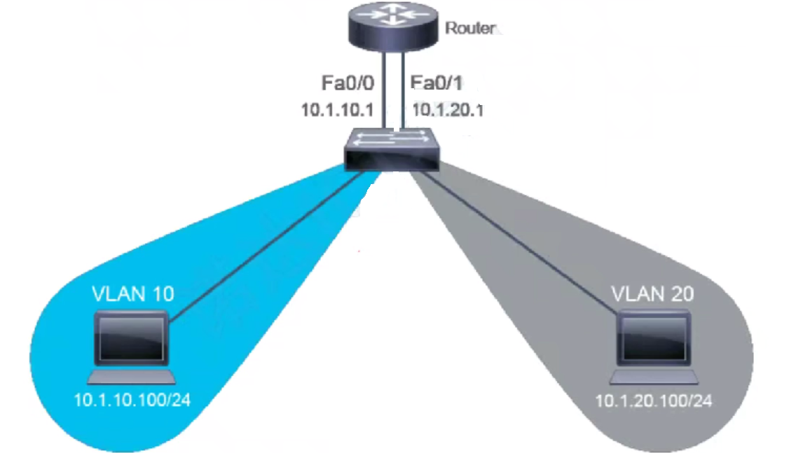
但这同样有一个问题,就是一个 VLAN 需要占用一个路由器上的接口,那么,能不能向交换机的 Trunk 口那样,在一个接口上跑所有的 VLAN 呢。
答案是肯定的,就是通过子接口的概念,将一个物理接口虚拟成多个子接口,并且为每个子接口配置一个 VLAN。这一技术也称为单臂路由。
简单来说,单臂路由是指在路由器的一个接口上通过配置子接口(逻辑接口)的方式,实现原来相互隔离不同的 VLAN 之间的互联互通。
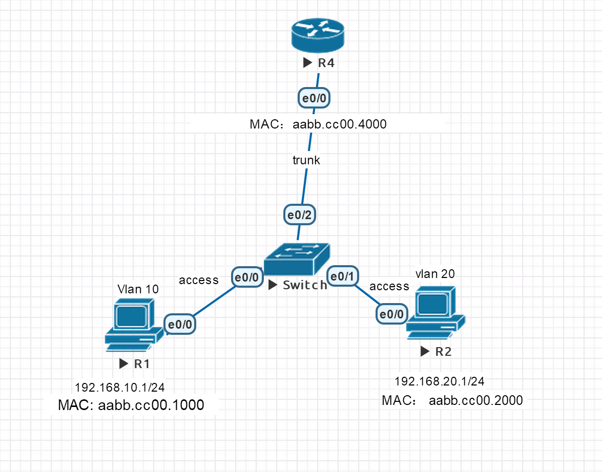
配置单臂路由:
#  Switch
Switch>en
Switch#conf t
Switch(config)#vlan 10,20
Switch(config)#int e  0/0
Switch(config-if)#switchport mode ac
Switch(config-if)#switchport mode access
Switch(config-if)#switchport access vlan 10
Switch(config)#int e  0/1
Switch(config-if)#switchport access vlan 20
Switch(config-if)#no shu
Switch(config-if)#int e 0/2
Switch(config-if)#switchport trunk encapsulation dot1q
Switch(config-if)#switchport mode trunk
Switch(config-if)#no shu

# PC: R1
Router>en
Router#conf t
Router(config)#no ip routing
Router(config)#ho R1
R1(config)#ip default-gateway 192.168.10.254
R1(config)#int e 0/0
R1(config-if)#ip add 192.168.10.1 255.255.255.0
R1(config-if)#no shu
R1(config-if)#do wr

# PC: R2
Router>en
Router#conf t
Router(config)#no ip routing
Router(config)#ho R2
R2(config)#ip default-gateway 192.168.20.254
R2(config)#int e 0/0
R2(config-if)#ip add 192.168.20.1 255.255.255.0
R2(config-if)#no shu
R2(config-if)#do wr


# Router: r4
Router>en
Router#conf t
Router(config)#ho r
r(config)#int e0/0
r(config)#no shu

# configure sub-interface 10
r(config)#int e0/0.10
# config vlan for this sub-interface
r(config-subif)#encapsulation dot1Q 10
r(config-subif)#ip add 192.168.10.254 255.255.255.0
r(config-subif)#no shu

# configure sub-interface 20
r(config)#int e0/0.20
r(config-subif)#encapsulation dot1Q 20
r(config-subif)#ip add 192.168.20.254 255.255.255.0
r(config-subif)#no shu
分析一下通讯过程:
R1 要给 R2 发送 ICMP,发现没有对应网关的 MAC 地址,将包搁置。发送 ARP 请求网关的 MAC 地址
Switch 学习后进行泛洪,R4 收到 ARP 请求,并做出 ARP 应答。
Switch 再次学习来自 R4 的 Arp 应答,并直接转发给 R1.
R1 解封装 ARP 应答包,并且将搁置的 ICMP 包添加 MAC 地址后,发出。
Switch 收到 ICMP 后,之间转发给 R4,R4 解封装发现 三层 IP 是给自己能到达网段的,进行封包:
4 层:ICMP 报头
3 层:IP 报头,源 IP 192.168.10.1/24 目的 IP 192.168.20.1/24
2 层: 源 MAC:aabb.cc00.4000 目的 MAC:不清楚
将包搁置,发送 Arp 请求 获取 R2 的MAC 地址
Switch 学习发来的 ARP 请求,并泛洪。R2 收到 Arp 请求做出应答,Switch 再次学习,然后直接转发给 R1。
R1 解析 ARP 应答,并将搁置的 ICMP 包发给 R2。
R2 又会做出 ICMP 应答,Switch 之间转发给 R1,R1 解封装发现 ICMP 的应答报文的目的 IP 是 R1,接着重新封装转发给 Switch。
Switch 再直接转发给 R1。
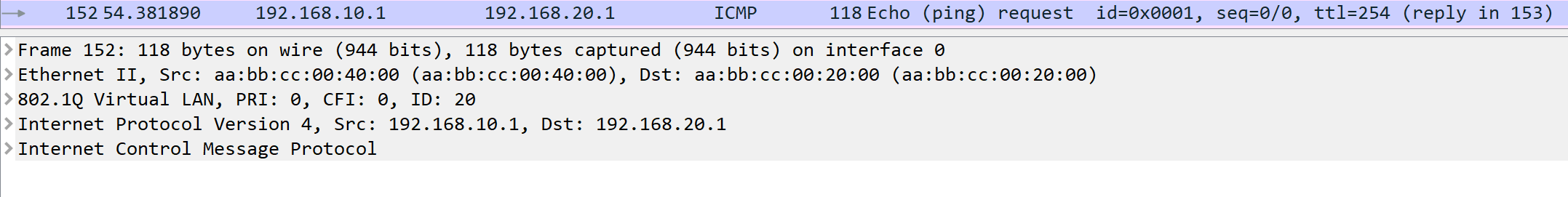
综上:我们可以发现一个有趣的现象,在 R4 和 交换机的链路上可以看到有双重的 Icmp 的 reqeust 和 reply 如下:
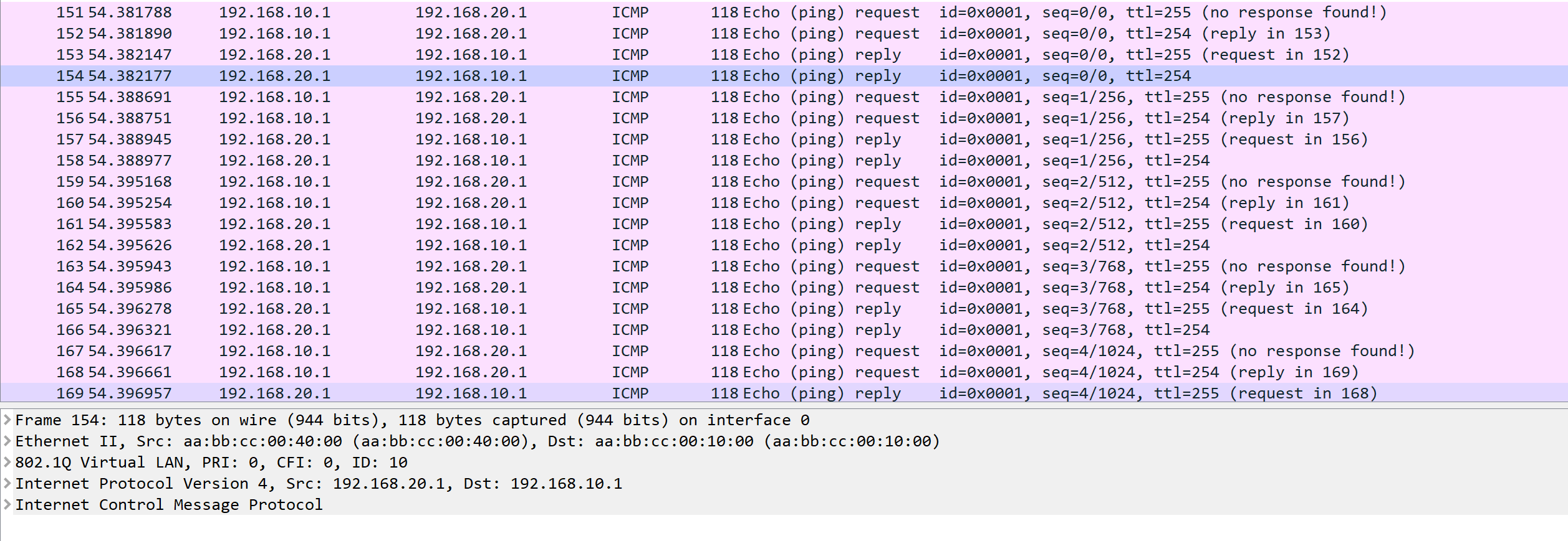
这里在解释一下两个 request 和 reply 的含义:
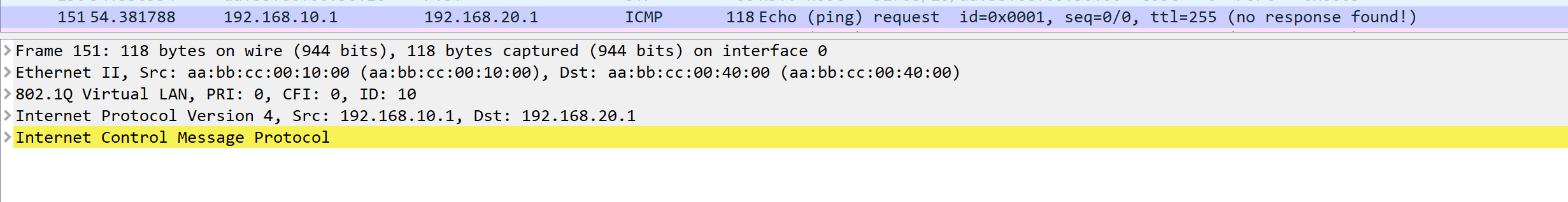
第一个 request 是:R1 发送 R4 (R4 是 R1 的网关) 并且应该带有 VLANID = 10 的 Tag,如下
第二个 request 是:R4 发给 R2 的 ICMP 包,并且应该带有 VLANID = 20 的 TAG,因为是从虚拟的子接口 Vlan20 发出,如下
第一个 reply 是:R2 发给 R4,带有 VLANID = 20 的 Tag,如下
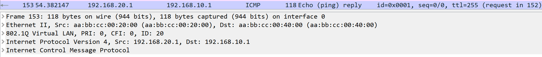
第二个 replay 是:R4 发给 R1 的,带有 VLANID = 10 的 TAG,如下
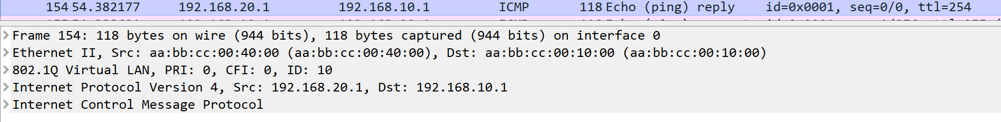
因此我们可以推测出在 R4 内部,进行了 Tag 的去除和封装。
SVI(Switch Virtual Interface)
另一种方式就是通过三层交换机,来达到路由转发的功能。
三层交换机,具有二层和三层转发的功能。
网关接口,用于三层交换机跨 VLAN 间路由,具体可以通过 interface vlan 接口配置命令来创建 svi,然后实现路由功能
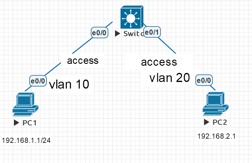
SVI 配置:
# switch
Switch(config)#ip routing    # 开启路由功能
Switch(config)#no ip cef    # 关闭cef(这个属于模拟器的bug,真实环境下不用)

# 创建 vlan
Switch(config)# vlan 10,20
# 配置模式
Switch(config-vlan)#int e 0/0
Switch(config-if)#switchport mode access
Switch(config-if)#switchport access vlan 10
Switch(config-if)#no shutdown
Switch(config-vlan)#int e 0/1
Switch(config-if)#switchport mode access
Switch(config-if)#switchport access vlan 20
Switch(config-if)#no shutdown

# 创建SVI接口
Switch(config)#interface vlan 10
Switch(config-if)#no sh
Switch(config-if)#ip address 192.168.1.254 255.255.255.0

Switch(config)#interface vlan 20
Switch(config-if)#no sh
Switch(config-if)#ip address 192.168.2.254 255.255.255.0

# PC
# 关闭路由功能
PC1(config)#no ip routing

# 配置 ip
PC1(config)#interface e0/0
PC1(config-if)#no sh
PC1(config-if)#ip address 192.168.1.1 255.255.255.0

# PC 配置网关
PC1(config)#ip default-gateway 192.168.1.254
由于是三层交换机,192.168.1.0/24 和 192.168.2.0/24 两个网段直接就可以互通了,不需要再去配置路由表,我们可以看一下路由表:
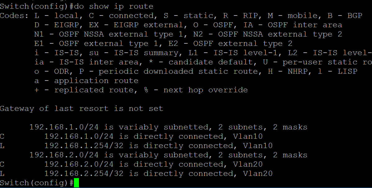
对三层交换机内部的讲解:
由于 e0/0 口是 access 口,所以会被打上相应 vlan ID=10 的 tag。
由于是三层交换机,通过 SVI 模拟路由器,也就是说明进行的是三层通信,可是传送过来的数据包中包含 tag,
也就说明存在一个能把 tag 拆掉的 access 口才能通信,所以推测这个口是虚拟的 Vlan 10,同时 Vlan 也是通往新网段的网关。
EtherChannel
有时交换机的带宽无法满足转发流量的需要,就会出现阻塞的情况。一般会升级接口的带宽,但有时往往特别大型的流量不是时常发生。手动的升级接口麻烦,甚至有些浪费。为了解决这个问题,EtherChannel 接口出现了,它可以将多个物理接口捆绑在一起同时进行流量的转发,在流量较大时增加连接接口的数量,从链路视角看,就是同时连接多根链路,实现并行传输。
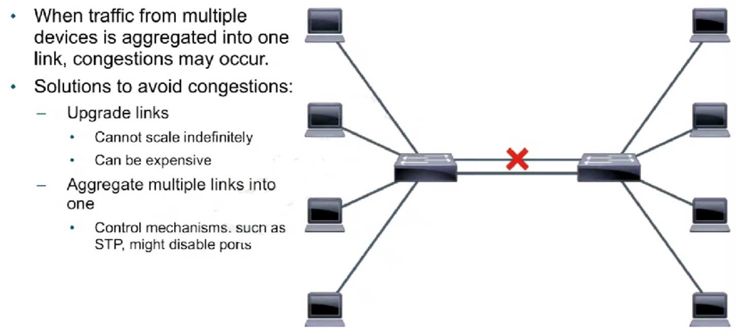
同时也出现了一个问题,在之前介绍交换机 STP 的内容时,了解交换机内部通过 STP 来防止环路,会将某些接口 Block。当如果想用这种并行的链路连接,就必须形成环路。
最后为了保证在 STP 不失效的情况下,应用并行链路,就会采用 EtherChannel 这种配置。会将所有绑定的接口视为同一个接口,这样 STP 还能正常的运行。
但想要实现 Port-channel 接口,需要保证所有的接口配置完全相同:
1、 物理接口支持 Etherchanbnel
2、 物理接口保持一致
3、 绑定的数量一致
4、 接口模式一样(如二层接口,三层接口)
5、 接口类型必须相同(带宽)
6、 双工,
7、 工作模式,trunk,switch
8、 vlan 相同
配置了 EtherChannel 的接口,具有如下优点:
- 逻辑聚合接口
- 高带宽
- 负载均衡
- 为 STP 提供一个逻辑接口
- 冗余(在断开下,仍能保持运行)
配置 EtherChannel
配置 EtherChannel 有两种方式:
1、 手动
* 手动将交换机上多个端口,捆绑成一个
2、 自动学习(PAGP思科私有,LACP公有)
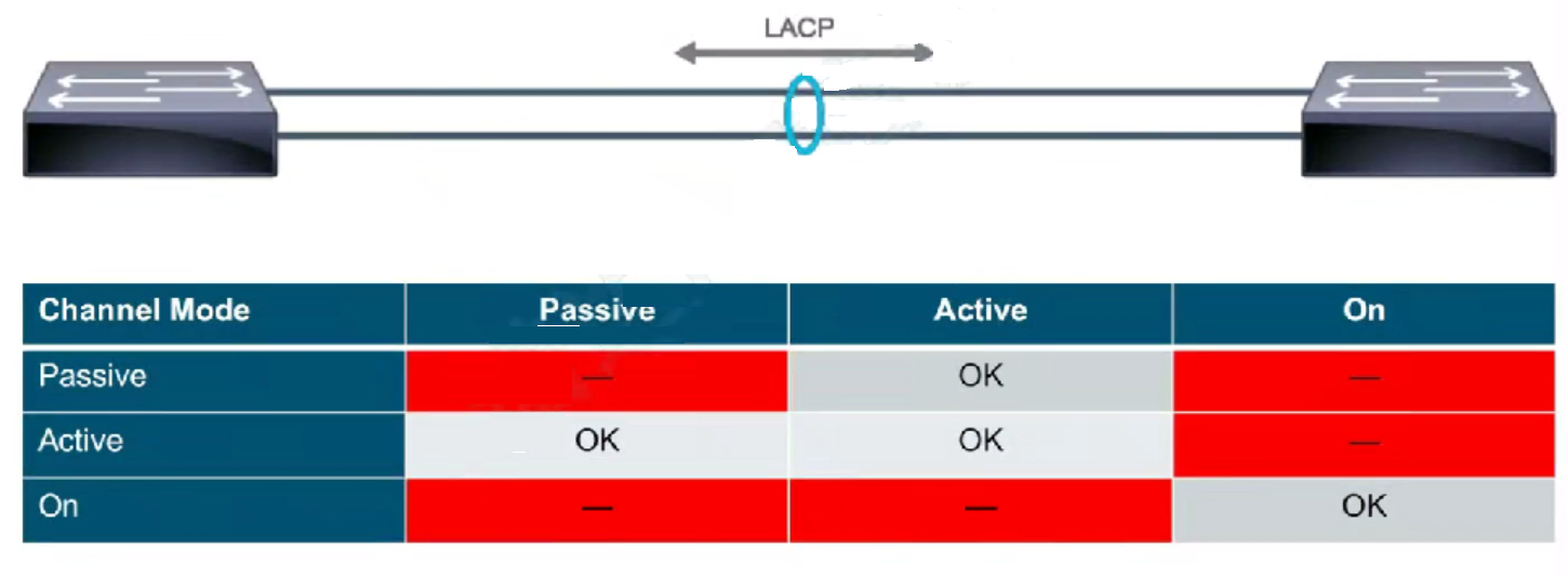
LACP 的模式:
- Passive:等待主动的接口,建立连接
- Active:主动发送消息,和另一端的接口建立连接
下面是 LACP 的建立原则:
# bind interfaces
s1(config)#interface range ethernet 0/0 - 1
s1(config)#shutdown
s1(config)#channel-group 1 mode active
s1(config)#no shutdown
# apply configuration
s1(config)#interface port-channel 1
s1(config)#switchport trunk encapsulation dot1q
s1(config)#switchport mode trunk

s1#show ip int bri
s1#show etherchannel summary

# bind interfaces
s2(config)#interface range ethernet 0/0 - 1
s2(config)#shutdown
s2(config)#channel-group 1 mode active
s2(config)#no shutdown
# apply configuration
s2(config)#interface port-channel 1
s2(config)#switchport trunk encapsulation dot1q
s2(config)#switchport mode trunk

s2#show ip int bri
s2#show etherchannel summary
总结
这篇文章中主要提到了三种技术:
- 单臂路由和 SVI 是为了解决 VLAN 在不同网段间通信的问题。
- EtherChannel 是为了解决物理端口带宽不够时,如果去调整的方案。